The Symbols - hydraulics and pneumatics command contains elements that are used in creation of hydraulics and pneumatics schemes.
Creating installation schemes is associated with drawing lines, inserting symbols and describing drawings. CADprofi program gives to the designer, the appropriate commands, that make it easier to describe scheme elements, thanks to which it is possible to create BOMs from the symbols and lines that are used in projects.
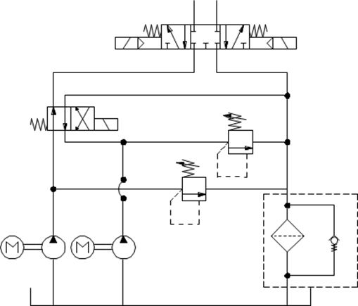
An exemplary scheme
All symbols available in CADprofi program are being inserted as blocks, which can be copied, deleted or edited with the use of standard CAD program commands. Most symbols can be also edited with the use of CADprofi editing commands such as: Quick edit, Edit symbols and Delete symbols.
Symbols are often used to graphically represent real devices, armature and other installations elements, therefore it is possible to add technical parameters, about the products used in the project, to the symbols (Attributes and descriptions command), as well as numbering and symbols' marks. This information can be used when describing drawings when creating graphical legends or specifications.
Program possesses several options that make it easier to insert symbols in the drawing.
|
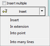
Main options (available after pressing the
•Insert symbol. •Into many lines. •In extension. •Into point. |
|
‘Insert symbol’ option
This is the default option that allows to insert symbols in any point or into a line indicated by user. When inserting symbols into lines, the symbol insertion angle depends on the line angle (the angle specified in the dialog box is being ignored).
6 Procedures
1. Select the symbols from any library.
2. Click the Insert symbol button. The library dialog window will close allowing insertion of symbol into the drawing.
3. Point into a line, in which you would like to insert the symbol.
4. (Optional) Click anywhere in the drawing to insert a symbol.
5. (Optional) Specify the rotation angle of inserted symbol - this option is available only if user has selected the Rotate option in the library dialog window.
|
| |
|
Insert into a line |
Insert in any point |
‘Into point’ option
The Into point option may be used when it is necessary to insert the symbol in a point that lies on a line, but in such a way that the symbol won't "adjust itself to the line". In this option, the inserted symbol "ignores" the line, so it does not break it and it does not take angle from it. This option is used in many situations for example when inserting sensors, which usually need to touch lines.
6 Procedures
1. Select the symbols from any library.
2.
With the use of  button,
pull-down the insertion list.
button,
pull-down the insertion list.
3. Click the Into point button and insert the symbol into the drawing.
4. Point into a point in a line, in which you would like to insert the symbol.
5. (Optional) Click anywhere in the drawing to insert a symbol.
6. (Optional) Specify the rotation angle of inserted symbol - this option is available only if user has selected the Rotate option in the library dialog window.

Inserting a symbol without adjusting it into the line
‘In extension’ option
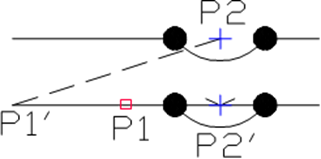
The In extension option allows to precisely specify the symbol insertion point in relation to other objects located in the drawing. This allows to insert a symbol in a point in accordance with for example another symbol.
6 Procedures
1. Select the symbols from any library.
2.
With the use of button,
pull-down the insertion list.
3. Click the In extension button. The library dialog window will close allowing insertion of symbol into the drawing.
4. Click a line, in which you would like to insert the symbol (P1).
5. Specify the symbol insertion point against you would like to specify the location of the inserted element (P2).
6. Specify an additional offset or click Enter to confirm the insertion point.
7. (Optional) Specify the rotation angle of inserted symbol - this option is available only if user has selected the Rotate option in the library dialog window.
8. Symbol will be inserted in the drawing and the command will end (if user has not selected the Insert multiple option).
Inserting in extension
‘Into many lines’ option
Into many lines option gives the possibility to quickly insert selected symbol into many lines.
It allows to insert selected symbol into all lines that cross with the „indication line”, that was specified during insertion (P1-P2).

Inserting symbols into many lines
6 Procedures
1. Select the symbols from any library.
2.
With the use of button,
pull-down the insertion list.
3. Click the Into many lines button. The library dialog window will close allowing insertion of symbols into the drawing.
4. Specify the first point of the “crossing line” that will cross with lines (P1).
5. Specify the second point of the “crossing line” that will cross with lines (P2).
6. The selected symbol will be inserted in all lines that crossed with the “crossing line”.
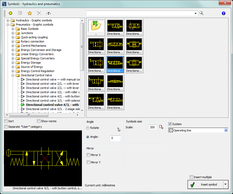
Symbols - hydraulics and pneumatics dialog window
The Symbols - hydraulics and pneumatics dialog window contains the following elements:
Tools menu:
 Define
new - allows to add a new element to the database. Read more about
it in the Defining user
blocks.
Define
new - allows to add a new element to the database. Read more about
it in the Defining user
blocks.
 Edit - allows to Editing user block parameters.
 Add to
favourites - copies symbol to the *Favourites*.
Add to
favourites - copies symbol to the *Favourites*.
 Delete - deletes the selected symbols from the *Favourites* category.
|
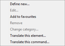
Pop-up menu - options menu for the selected symbol, which is available after right clicking on the mouse button on the selected symbol. Commands in this menu are similar to the tools menu. |
|
Category tree - a set of all categories and symbols in the library, shown as a pull-down tree. User can customize the display order by using the following options:
•Sort - alphabetical order of categories placement and their content.
•Norms- enables/disables displaying symbols according to norms.
Thumbnail view - displays the content of currently selected category as thumbnails.
Preview - displays the preview of the currently selected symbol. Right-clicking on the preview window will zoom the view.
Angle/Rotation - possibility to specify a fixed angle when inserting an element or enabling the rotation option, in which element’s angle is defined by rotation during insertion.
Scale - specifies the size of inserted symbols. It is possible to enter the scale value or to indicate a symbol on the drawing whose scale user would like to use.
System - if in the program options, the extended layer name structure is enabled then symbols will be inserted on layers depending on the kind of installation (system). In case of inserting symbols into an existing line then the System option is being ignored and the symbol layers depends on the line kind.
Mirror X, Y- enabling this option will create an X or Y mirror image for the specified object.
Insert multiple- enables/disables the possibility of inserting multiple symbols to the drawing. The insertion process requires from the user to press the Enter or Esc key when he finished inserting multiple symbols.
6 Procedures
If you can provide any additional context, such as the file format (e.g., PDF, RAR) or the type of content you expect (e.g., fashion, tech, academic), I can help you further refine the search.
Here’s a short, useful story:
: Ensure you are of legal age to access any content you might find. Many countries have laws restricting access to adult content for those under a certain age (often 18 or 21).
If this is a real file you've encountered in a database, the content should be structured as technical documentation. Item Title: LS Magazine: Issue 19 (Digital Archive) Serial Code: 911-3000-FOTO Patched / Restored Description: lsmagazineissue 19 9113000foto patched
For those interested in learning more about LSMagazine, the 911/3000, or simply appreciating exceptional automotive content, Issue 19 is an invaluable resource. Whether you're a seasoned collector or simply a car enthusiast, LSMagazine Issue 19 and the 911/3000 Foto Patched are sure to captivate and inspire.
The term "Foto Patched" adds an air of intrigue, suggesting that the feature might be related to a unique visual project or a creative photoshoot. While details are scarce, it's clear that this feature will be a highlight of Issue 19.
A "lost" digital magazine issue from the late 90s that was supposedly corrupted but has now been "patched" by a mysterious source. 13.60.92.105 Patched - Lsmagazineissue 19 9113000foto If you can provide any additional context, such
Seeking out strings like this—especially when they combine known illegal terms ("lsmagazine") with "patched"—exposes you to multiple risks:
While the true meaning behind "9113000foto patched" remains unclear, it's essential to consider the broader significance of Issue 19 within the context of LSMagazine's history. This issue might represent a turning point or a milestone in the publication's evolution, marking a shift towards more experimental or avant-garde content.
As online publications continue to push the boundaries of what is considered acceptable, it's essential to examine the impact of such content on readers. While some may argue that LSMagazine Issue 19 is a form of free expression, others have raised concerns about the potential harm it may cause. If this is a real file you've encountered
LSMagazine Issue 19, with its feature on the 911/3000 Foto Patched, holds a special place in the hearts of car enthusiasts. This issue not only showcases a rare and unique vehicle but also demonstrates the publication's commitment to preserving and sharing the stories of exceptional cars.
Lo-fi, grain-heavy photography (FOTO) featuring models in "patched" clothing (DIY, punk, or upcycled aesthetic).
In legitimate contexts, patching refers to software updates that fix vulnerabilities. However, in underground file-sharing circles, "patched" often means:
To understand the significance of LSMagazine Issue 19, it's essential to explore the history of the publication. LSMagazine has been circulating online for years, often featuring a mix of articles, images, and other content that pushes the boundaries of what is considered acceptable.

 Creating
pneumatic
schemes
Creating
pneumatic
schemes